Point: The LM1458N is a general-purpose dual op amp with modest speed and drive, requiring realistic design expectations. Evidence: Typical supply range is 6–36 V, quiescent current ~3 mA, slew rate ≈0.5 V/µs, and output drive limited to a few tens of mA. Explanation: These specs define its suitability for audio preamps and basic analog tasks where cost-efficiency is prioritized over high-speed precision.
Point: Understanding datasheet context prevents performance mismatches in real-world circuits. Evidence: Rated parameters fluctuate based on load, supply, and temperature. Explanation: Factors like noise, bandwidth, and output swing relative to the rails determine if the LM1458N meets specific application requirements.
1 — What the LM1458N Is and Where It Fits
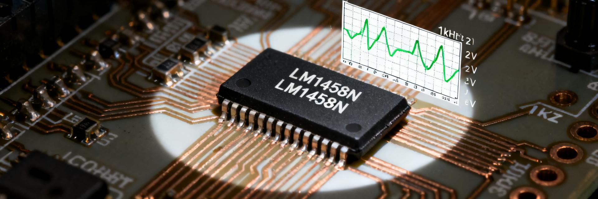
Core architecture & functional overview
Point: The LM1458N utilizes a classic dual bipolar-input architecture with a push-pull output stage. Evidence: The internal topology is a standard two-stage design with internal compensation yielding ~1 MHz bandwidth. Explanation: This results in predictable behavior for low-cost audio and active filters where high speed is not a critical constraint.
2 — Key Electrical Specs: Read the Numbers Correctly
| Parameter | Typical | Min | Max / Test Conditions |
|---|---|---|---|
| Supply Voltage (Vcc) | ±3 to ±18V | ±3V | ±18V (Single 6–36V) |
| Quiescent Current | ≈3 mA/pkg | — | Per datasheet standards |
| Slew Rate | 0.5 V/µs | — | Vcc = ±15V, RL=2kΩ |
| Unity-Gain BW | 1.0 MHz | — | Typical, 25°C |
3 — Performance Limits & Failure Modes
Point: Absolute maximums and thermal boundaries define the safe operating envelope. Evidence: Exceeding package power dissipation or operating near rail limits without current limiting leads to thermal runaway. Explanation: Designers must implement adequate decoupling and PCB thermal planning to prevent catastrophic failures during short-circuit conditions.
4 — How to Benchmark the LM1458N
Recommended test circuits
Point: Standardized test rigs ensure repeatable performance metrics. Evidence: Use unity-gain buffers for slew measurements and closed-loop configurations for THD and bandwidth. Explanation: Documenting RL (e.g., 2kΩ) and supply rails is critical to differentiate measurement artifacts from actual device behavior.
5 — Benchmarks & Real-World Results
Point: Observed bench results typically align with datasheet tolerances with minor variation. Evidence: Typical slew rates of 0.4–0.6 V/µs and output drive of ~40mA are common in stabilized test environments. Explanation: Analyzing Bode plots and THD vs. amplitude reveals the practical distortion limits for specific audio or filter applications.
6 — Actionable Recommendations
- Verify supply headroom against the required output swing to avoid clipping.
- Compensate for input bias (100s of nA) when interfacing with high-impedance sensors.
- Use external buffers if the application requires driving low-impedance loads below 2kΩ.
- Monitor junction temperature if operating at the maximum 36V supply limit.
Summary
- The LM1458N is a reliable, cost-effective dual op amp for non-critical analog stages.
- Key constraints include a 1 MHz bandwidth, 0.5 V/µs slew rate, and standard bipolar input bias.
- Bench testing with standard loads is essential to validate performance before mass deployment.
FAQ
How does the LM1458N input bias affect sensor front-ends?
Point: Input bias current can introduce significant error in high-impedance circuits. Evidence: Bias currents in the 100s nA range create offset voltages across source resistances. Explanation: Use bias compensation or lower source impedance to maintain DC precision.
What are the typical output drive limits of the LM1458N?
Point: Output drive is sufficient for light loads but limited for high-current needs. Evidence: Practical limits are typically 30-50 mA before voltage sag. Explanation: Add an external transistor buffer for heavy loads or low-impedance transducers.
When should a designer replace the LM1458N due to limits?
Point: Replace when speed or rail constraints bottleneck system performance. Evidence: Requirements for rail-to-rail swing or >1V/µs slew indicate the need for an upgrade. Explanation: Shift to higher-performance FET-input or high-speed op amps for demanding transient fidelity.
What are the thermal considerations for LM1458N reliability?
Point: Thermal management is critical at high supply voltages. Evidence: Package dissipation increases significantly at ±18V operation. Explanation: Ensure PCB layout includes sufficient copper for heat dissipation and avoid continuous short-circuit conditions.




